Shear Force and Bending Moment in Beams (Civil Engineering)
In civil/structural engineering, shear force (V or SF) and bending moment (M or BM) are internal forces that develop in beams due to external loads, supports, and moments. They are essential for designing beams to resist failure in shear or bending.
Definitions
- Shear Force (SF): The algebraic sum of all vertical forces acting to one side (left or right) of a section. It represents the tendency to shear/slide one part of the beam past the adjacent part.
- Bending Moment (BM): The algebraic sum of moments of all forces acting to one side of a section about that section. It causes the beam to bend (hogging or sagging).
Key Relationships
These come from equilibrium equations:
- The rate of change of shear force equals the negative of the distributed load intensity: (where is the distributed load per unit length).
- The rate of change of bending moment equals the shear force:
This means:
- Slope of SF diagram = -load intensity.
- Slope of BM diagram = shear force.
- Area under load diagram = change in shear.
- Area under SF diagram = change in BM.
Sign Conventions (Common in Engineering)
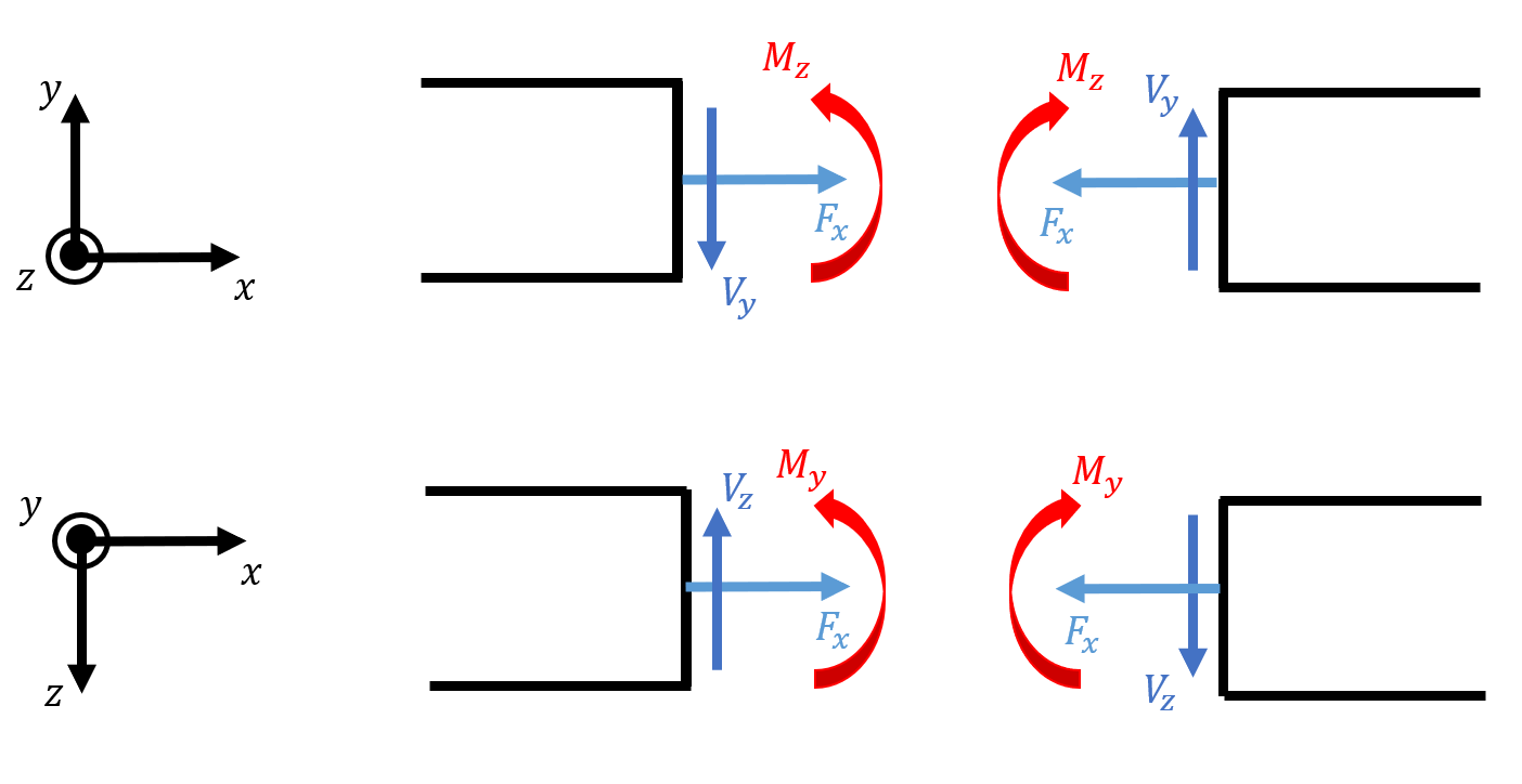
Typical conventions:
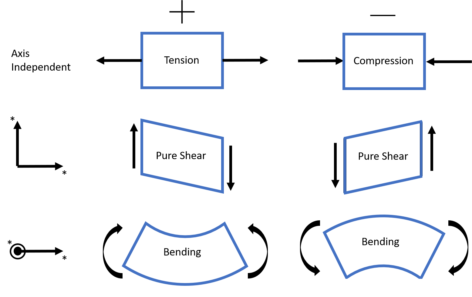
- Positive shear: Left side upward or causes clockwise rotation of the section.
- Positive bending moment: Causes compression on top fibers (sagging in simply supported beams, often drawn as "smiling").
Shear Force Diagram (SFD) and Bending Moment Diagram (BMD)
These graphical plots show variation along the beam length. They help identify maximum values for design.
Common Examples
- Simply Supported Beam with Central Point Load
- SFD: Constant positive shear on left half, jumps down at load, constant negative on right half.
- BMD: Linear increase to maximum at center, then decrease to zero at ends (triangular shape).


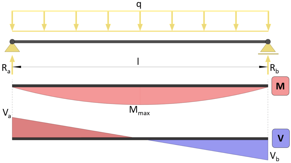
- Simply Supported Beam with Uniformly Distributed Load (UDL)
- SFD: Parabolic (maximum at ends, zero at center).
- BMD: Parabolic (maximum at center).
Simply Supported Beam – Moment & Shear Force Formulas Due To ...
- Cantilever Beam with Uniformly Distributed Load (UDL)
- SFD: Linear (zero at free end, maximum at fixed end).
- BMD: Parabolic (zero at free end, maximum at fixed end).


Visual Relationship Between Load, Shear, and Moment

To draw SFD/BMD:
- Calculate support reactions.
- Section the beam and use equilibrium to find V and M expressions in segments.
- Plot the diagrams.
These diagrams are foundational for beam design in civil engineering, determining reinforcement in RCC, section modulus, etc. For complex loads, use tools like free beam calculators.
Tags:
Strength of Materials